2025.10.09
CTI Engineering improves the functions of its 3D Design Support System, thereby promoting the increased efficiency and quality of design business: CTI Engineering's design innovations and next-generation standards
Technology & Research
Our company has developed and used 3D Design Support System Ver. 1 to increase the efficiency and quality of in-house production while also promoting BIM/CIM.
We recently added new functions during the development of 3D Design Support System Ver. 2 and subsequently launched our in-house operations. This will enable further increases in design efficiency and sophistication.
1. Background
Starting in fiscal 2023, in order to use 3D data to increase the efficiency and sophistication of the construction and production processes for civil engineering business and construction done by the Ministry of Land, Infrastructure, Transport and Tourism, the use of BIM/CIM was made mandatory in general. However, up until now, because designing has been accomplished by creating 3D models after completing the corresponding 2D drawings, it has been difficult to reap all the potential benefits of utilizing 3D data.
To resolve this problem, our company developed a system that utilizes 3D models starting at the initial stages when designing bridge substructures (structures that distribute the load from the superstructure to the foundation) as well as sluice gates and sluice pipes (structures buried across the inside of levees for drainage purposes).
We launched in-house operations of this system starting with Ver. 1 in 2021, thereby increasing design efficiency and quality (Fig. 1).

Fig. 1 Design process utilizing 3D models
The features of the tools used to expand the functions of Ver. 2, which we recently released, are as follows:
- For bridge substructures, added a design support function for bridge abutments (substructure elements located at each end of a bridge)
- For sluice gates and sluice pipes, added 3D bar arrangement modeling and 2D bar arrangement drawing creation functions
2. Developed technology features
This system relies primarily on 3D data and can be used to update data while linking 2D drawings, design calculation software, and quantity calculation sheets (Fig. 2).
The updated 3D data is then saved to the cloud so that it can be utilized when we design new structures of the same type. This enables more efficient design work.

Fig. 2 System configuration diagram
Thanks to the functional enhancements for Ver. 2, the structural dimensions and shape data of bridge substructures (including bridge abutments, bridge piers, and foundations) as well as sluice gates and sluice pipes can be linked to 3D CAD software and structural calculation software to achieve both 3D modeling (structures and bar arrangement) and the creation of 2D drawings (Fig. 3).
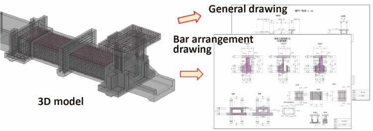
Fig. 3 Automatically generating 2D drawings based on a 3D model
This system is being used for actual business, and it utilizes 3D models to make it easy to visualize the placement of structures, significantly reduces the working hours necessary to prepare design drawings (about 60%), and offers other benefits.
3. Effects of system introduction and future outlook
Accumulating system utilization examples makes it possible to accumulate knowledge, pass down skills when transitioning to the next generation of engineers, and ultimately increase design efficiency and sophistication.
We plan to further expand the system application range by increasing the types of structures the system can handle, as well as through other improvements.